

Instrument signature removal (ISR)#
ISR is the first step of image processing, which removes instrumental effects introduced in the raw images by the telescope and detectors and produces an accurate representation of the incoming light.
Users should not attempt to recreate or rerun ISR, and a full understanding of the components and subtleties of ISR is not necessary in order to use the data products.
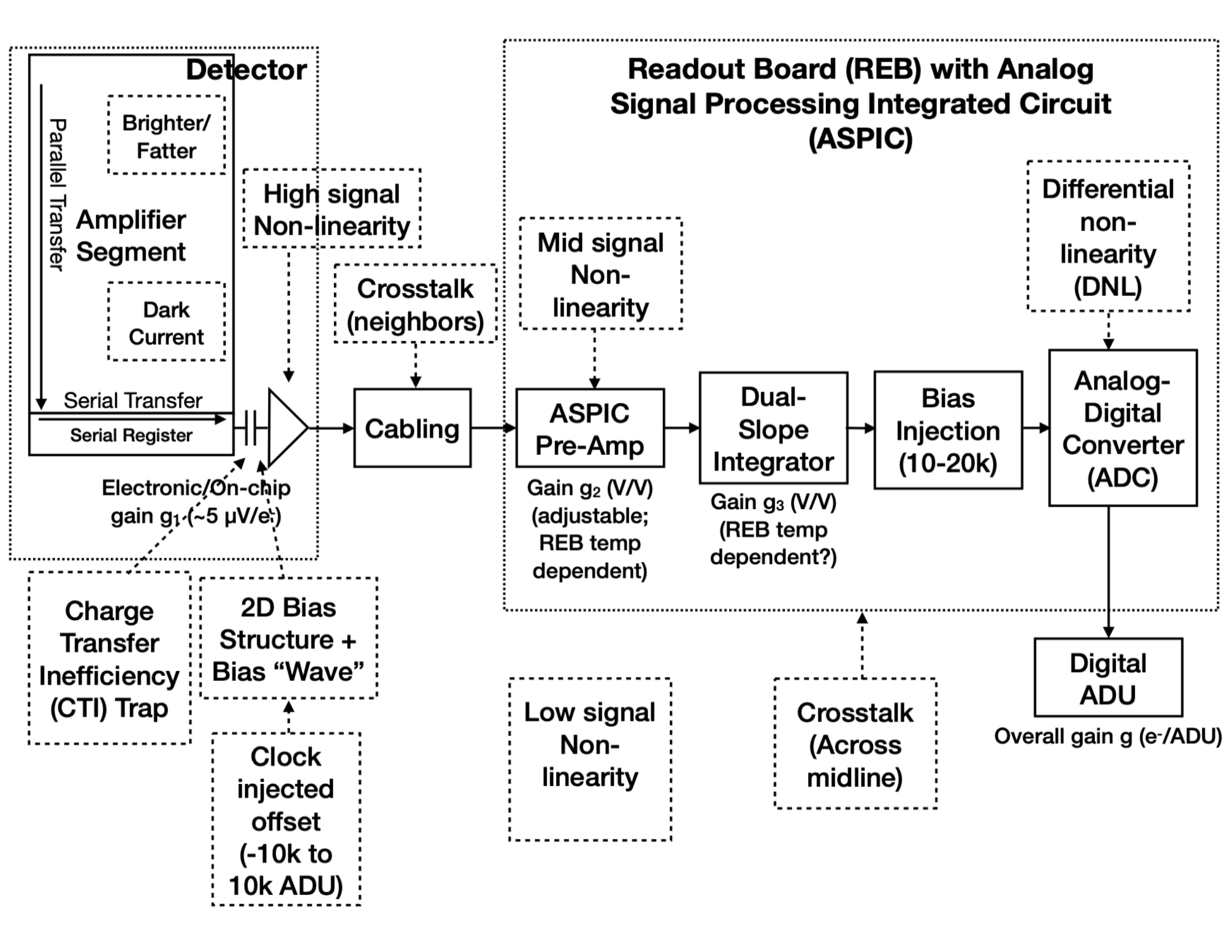
Figure 1: Photon transfer and data-acquisition model for the LSSTCam detectors and readout electronics board (REB), labeled with the instrumental effects (dashed boxes) and where each enters the chain. Low-signal non-linearities have been observed in the detector response, but their origin is not yet established, so that contribution appears as a disconnected box (from RTN-117).#
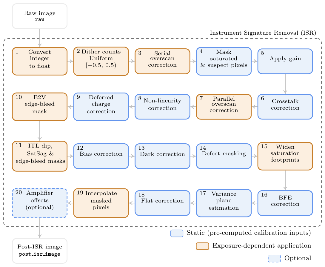
Figure 2: Outline of the Instrument Signature Removal pipeline applied to LSSTCam science images for DP2, derived from the detector model in Figure 1. Blue boxes denote static steps that apply pre-computed calibration inputs; orange boxes denote steps whose application depends on the science exposure itself; white boxes mark the raw input and post-ISR output; and the dashed box is an optional step (from RTN-117).#
Components#
The steps of ISR, in the order they are applied to DP2 science images, include (from RTN-117; see also Plazas Malagón et al. 2025):
Conversion from integer to float: promotes the raw integer pixel values to floating-point precision before any corrections are applied.
Dithering of digitized counts: adds a uniform random offset in the range [−0.5, 0.5) analog-to-digital units (ADU) to every pixel to mitigate quantization bias introduced by analog-to-digital conversion.
Serial overscan subtraction: removes the electronic, clock-injected offset and smaller row-to-row variations using the serial overscan region, while the data are still in ADU.
Masking of saturated and suspect pixels: flags pixels above the saturation threshold, derived from the photon transfer curve (PTC) turnoff, in the pixel mask before further corrections, preventing corrupted values from biasing downstream estimates.
Gain scaling: converts pixel values from ADU to electrons using per-amplifier gains derived from the PTC.
Crosstalk correction: removes electrical coupling between amplifier outputs using a pre-measured crosstalk matrix, applied in electron units consistent with how the matrix was measured.
Parallel overscan subtraction: subtracts a column-wise estimate of the readout offset using the parallel overscan region; it follows crosstalk correction because amplifier coupling can inject signal into the overscan regions.
Non-linearity correction: corrects the non-linear detector response using a double-spline linearizer that maps measured counts to linearized electron counts.
Deferred charge (CTI) correction: removes residual charge left in pixels during serial readout, arising from global charge transfer inefficiency (CTI), local electronic offsets in the output amplifier, and serial charge traps on ITL sensors; E2V sensors are not corrected because their deferred charge is already below requirements.
E2V edge-bleed masking: flags pixels in E2V amplifiers affected by uncorrectable charge spill from bright regions at the serial-register edge.
ITL dip, SatSag, and edge-bleed masking: flags ITL-specific artifacts — a column response depression near certain amplifier boundaries (the “ITL dip”), a sag in apparent signal after saturation (“SatSag”), and edge bleeding analogous to the E2V case.
Bias subtraction: subtracts a combined bias frame created from multiple zero-time exposures, removing the fixed-pattern electronic offset that remains after overscan subtraction.
Dark subtraction: subtracts the combined dark frame, scaled by the science exposure time, removing the thermal dark current accumulated during the exposure.
Defect masking: merges persistent bad pixels, columns, and other static defects identified during calibration into the pixel mask.
Widening of saturation footprints: expands the saturation mask to include neighboring pixels affected by charge spill and trails from saturated sources.
Brighter-fatter correction: redistributes flux among neighboring pixels to undo the electrostatic “brighter-fatter” effect (where brighter sources appear larger), using a kernel calibrated from flat-field pixel correlations.
Variance plane estimation: assigns an expected variance to each pixel from the Poisson noise and the PTC-derived read noise, creating a map for uncertainty propagation in later processing.
Flat fielding: divides the image by the normalized flat field to correct pixel-to-pixel variations in quantum efficiency and optical throughput.
Interpolation over masked pixels: fills saturated and bad pixels with values interpolated from neighboring unmasked pixels, so that downstream algorithms that assume a continuous image operate on calibrated flux units.
Amplifier offset correction (optional): applies small per-amplifier adjustments derived from flat-field residuals to reduce remaining flux discontinuities at amplifier boundaries.
Overview#
Each sensor and its readout amplifiers can vary slightly in performance, causing images of even a uniformly illuminated focal plane to exhibit discontinuities and shifts due to detector effects. Figure 1 illustrates the photon transfer and data-acquisition model of the detector components and their impact on the signal, tracing the process from photons incident on the detector surface to the final quantized values recorded in the image files. Based on this model, a series of Instrument Signature Removal steps are implemented to eliminate camera-induced effects (Figure 2).
The ISR pipeline essentially “works backward” through the signal chain, applying corrections in reverse chronological order relative to the photon transfer chain and converting the integer analog-to-digital units (ADU) of the raw camera output back to a floating-point number of photoelectrons created in the silicon. The physical detector, shown on the left in Figure 1, is the source of effects that arise from the silicon itself, such as the dark current and the brighter-fatter effect (Broughton et al. 2024, Gruen et al. 2015).
After the image has integrated, the charge is shifted to the serial register and read out, which can introduce charge transfer inefficiencies and a clock-injected offset level. The signals for all amplifiers are transferred via cables to the Readout Electronics Board (REB), during which crosstalk between the amplifiers may occur. The Analog Signal Processing Integrated Circuit (ASPIC) on the REB converts the analog signal from the detector into a digital signal, adding both quantization and a bias level to the image. Although the signal chain is designed to be stable and linear, the presence of numerous sources of non-linearity reveals its complexity.
Because effects are undone in the opposite order to which they were imprinted, steps that undo readout-electronics effects appear before steps that undo detector-level effects, and additive corrections precede multiplicative ones such as flat-fielding. Quantization is addressed first through count dithering, followed by serial overscan subtraction, saturation masking, and gain conversion to electrons. Crosstalk is then corrected to prevent its contamination of later steps like parallel overscan subtraction and non-linearity correction, and deferred charge (CTI) is corrected next, followed by vendor-specific masks for artifacts such as edge bleeds and the ITL dip. The final steps include bias and dark subtraction, defect masking, brighter-fatter correction, variance plane construction, flat-fielding, and interpolation over masked pixels. Each of these steps is tied to specific elements in the detector readout chain; running the pipeline with misplaced steps would either apply a correction in the wrong physical units or leave residual structure that invalidates downstream calibrations (RTN-117, Plazas Malagón et al. 2025).
Subtleties#
Amplifier offsets#
Through much of DP2 processing, there were amplifier offsets that propagated through to photometry and PSF residuals. The optional “amp offset correction” step, which applies small pre-computed per-amplifier adjustments derived from flat-field residuals, was enabled to mitigate this issue. While this correction is not fully principled, it appears to work on average with no evidence of pathological behavior so far.
Camera sequencer changes#
Three different camera sequencer configurations were used during the DP2 observing period:
“2s_v30” sequencer (April 2025 through July 2, 2025): 2+ second readout, with extra noise in some E2V sensors and most ITL amplifiers, and random gain jumps (~0.02% level) for some ITL amplifiers. Basic calibrations were derived from clean-room data.
“3s_v1” sequencer (July 2, 2025 through January 23, 2026): 3 second readout, with significantly reduced noise in both E2V and ITL amplifiers, though some unexpected even/odd pixel correlations in E2V noise remained. Random gain jumps (~0.02% level) for some ITL amplifiers persisted.
“3s_v2” sequencer (from January 23, 2026): not included in DP2.
These changes result in three calibration epochs (2025-04-24 to 2025-07-02, 2025-07-03 to 2025-09-21, and 2025-10-24 to 2026-01-06) with different noise characteristics. Flat fields improved with each successive epoch, and the y-band flats are notably better for the third epoch due to the installation of a new 1050 nm LED.
Flat fielding#
The flat-field screen is not uniformly illuminated, nor does it uniformly fill the focal plane. For each filter except u, two “anaglyph” flats are taken (one with a bluer LED and one with a redder LED), with special gradient-removal code to correct for gradients and centering. This correction does not work well in the outer partly vignetted region of the focal plane, and improved vignetting models are planned for future calibration epochs to reduce focal-plane non-uniformity.
Camera temperature variations (particularly during the second calibration epoch) and focal plane restarts also changed gains slightly, resulting in additional amplifier offsets.
Low-signal non-linearity#
The DP2 linearizer corrects the average amplifier non-linearity but does not yet apply a full low-signal differential non-linearity (DNL) correction, reflecting the difficulty of delivering flat-field illumination below 100 ADU/pixel with the in-dome calibration system. Count dithering in ISR provides interim mitigation, but users should exercise caution when relying on photometric or astrometric measurements at low signal levels, in particular u-band sky-background estimates, where backgrounds are typically at or below 100 ADU/pixel. In addition, small quasi-oscillatory residuals (“wiggles”) remain as a function of signal level after the non-linearity correction; these are well below current science requirements and are left uncorrected in DP2.
Brighter-fatter color dependence#
The brighter-fatter effect is color dependent because its amplitude depends on the photon conversion depth in the silicon. The correction used in DP2 applies a single wavelength-averaged kernel per detector, derived in the band of the PTC input flats; color-corrected calibrations, appropriate in particular for the z and y bands, were not enabled in DP2 and are expected for DR1. Until then, PSF photometry and shape measurements of bright sources, especially in redder bands, may retain small flux- and filter-dependent biases.
Fringing#
Fringing, an interference pattern driven primarily by night-sky emission lines in the z and y bands, is not fully canceled by flat-fielding, and the DP2 ISR pipeline does not include a dedicated fringe-subtraction step. Residual fringe structure is visible at low surface brightness in z- and y-band visit images and can bias wide-aperture photometry; fringe corrections are under development and expected for DR1.
Additional resources#
For descriptions of the ISR steps and the generation, verification, certification, approval, and distribution of the calibration products necessary for ISR, refer to the following:
“Image Calibration and Instrument Signal Removal for the First Year of the LSST” (RTN-117)
Instrument Signature Removal and Calibration Products for the Rubin Legacy Survey of Space and Time
“Rubin Baseline Calibration Plan” (SITCOMTN-086)
“Verifying LSST Calibration Data Products” (DMTN-101)
“Calibration Generation, Verification, Acceptance, and Certification” (DMTN-222)